Ask the Doctors! Drs. David P. Berners and Jonathan S. Abel Answer Your Signal Processing Questions.
 |
|
|
(A summary of many questions on the subject)
A: Alright, this is a big topic, and we'll answer the question in two articles. In this first part, we look at what "phase" means when you're talking about an EQ, and touch on the psychoacoustics of phase perception. Next month, we'll explore the meaning of linear phase, and how and why it's useful.
A Bit of Background
Let’s start by answering the more generic question “What is phase, and why should I care about it?” To begin, we need to address the broader topic of spectral analysis.
There is a class of signal-processing systems known as Linear Time-Invariant (LTI) Systems. The basic property of these systems is that for any two signals a(t) and b(t), if you process the two signals separately and add the results, the output will be indistinguishable from the case where you add a(t) to b(t) and then process the sum. In other words, for a signal processing function G{·} to be LTI, we have
The second property of the LTI system is that, no matter when we process a given signal, the system will behave in the same way. Stated mathematically, if the input is delayed by an amount d, the same output is also delayed by d,
(2) g(t - d) = G{a(t - d)}.
Examples of LTI systems include very clean EQ’s, reverbs, and delays, but not distortion effects, chorus/flangers, or compressors. This is why you can group tracks and send them to an EQ or reverb and have it sound the same as if you applied identical EQ or reverb to each track separately, and why this cannot be done with compression or distortion effects. (Note that not all EQs and reverbs are LTI. Analog EQs sometimes add a little color to the signal, and are therefore nonlinear; digital reverbs on occasion use delay lines having lengths which change over time to break up resonances, and are therefore time varying.)
It is commonplace to study LTI systems in terms of their effect on the spectrum of a signal. Why is this done? It turns out that LTI systems have the very special property that if you process a pure sine wave with an LTI system, the output will always be a sine wave at the same frequency. This is not true for any other waveform. For example, if you put a square wave into a lowpass filter, the output will not be a square wave! But if you put any sinusoid into a lowpass filter, what comes out will always be a scaled, time-delayed copy of that sinusoid.
In fact, we can characterize an EQ or other LTI system by defining its frequency response. This means that we want to know what is the scaling a(f) and time-delay t(f) that will be applied to every frequency sinusoid when it is processed by the system,
(3) a(f ) sin(2pf ·[t – t (f )]) = G{sin(2p f t)}.
By another amazing property of LTI systems, it turns out that once we know the amount of scaling a(f) and time-delay t(f) that will happen at all frequencies f, the system is fully defined! In other words, if we know the frequency response of an EQ, we have an exact description of what happens within that EQ.
One way to understand this incredible fact that the frequency response (a(f) and t(f)) completely describes any LTI system is to consider that as Fourier showed, every signal can be decomposed into a sum of sine waves. This decomposition is referred to as the signal’s spectrum or Fourier Transform. Now, by the linearity and time invariance properties of LTI systems – (1) and (2) above – we can compute the output of an LTI system to any signal by
- first breaking up the signal into a sum of sinusoids
- then separately applying the sinusoids to the LTI system by scaling and delaying according to the frequency response
- and then summing the delayed and scaled components to get the output signal.
So how does phase fit in to all this? It turns out that phase is a description of the time-delay which happens in our system as a function of frequency. The exact definition of phase delay is:
(4) t (f ) = q(f ) / (2p f ),
where t (f ) is the phase delay, and q(f ) is the phase at frequency f. Phase delay is convenient because it expresses the phase response of a system (or the phase of a signal), which ranges from zero to 360 degrees, as a time delay. So the units of phase delay are seconds, and it tells us how many seconds a sinusoid will be delayed when it goes through an EQ or other LTI system.
By the way, when talking about LTI systems, the expression "linear phase" refers to a frequency response where the phase q(f ) increases linearly with frequency f. Put mathematically, this means
(5) q(f ) = d · (2p f ),
for some constant d. Comparing this expression to (4), we see that linear phase is a pure time delay d, independent of frequency. A linear phase system, therefore, can adjust the amplitudes of the signal's frequency components without changing their relative time alignment.
Human Perception
The second part of the question is “Why do we care about phase?” This can sort of be re-phrased as “In what cases are we sensitive to phase?” or “When can we notice changes in phase?” It turns out that, for some steady-state signals, people are not all that sensitive to changes in phase.
 |
|
Figure 1
|
 |
|
Figure 2
|
 |
|
Figure 3
|
 |
|
Figure 4
|
- phase1.wav
- phase2.wav
- phase3.wav
- phase4.wav
- phase5.wav
- phase6.wav
- You may need to "right-click" or "click and hold" to download the files.
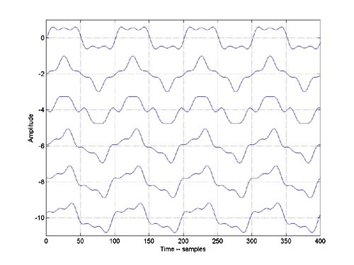
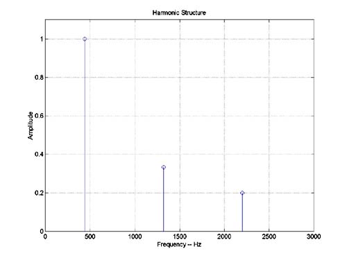
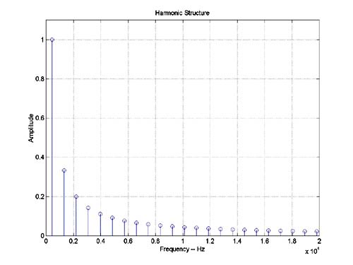
The difference between the waveforms is the relative phase between the three harmonics present in the signal. Although the time-domain waveforms look quite different, at low levels the signals are likely to sound similar. It is pretty easy to hear separately the three harmonics in this set of signals as approximately A4, E6, and C#7. Try downloading the files and making a session with each file on its own track. Loop playback on the files and try soloing each in turn. Going back and forth between files one and two will bring out the harmonic at E6, as its phase is different in these two files. Similarly, going between files two and three will bring out the harmonic at C#7. However, once the files are looping in steady state, they should sound pretty similar to each other.
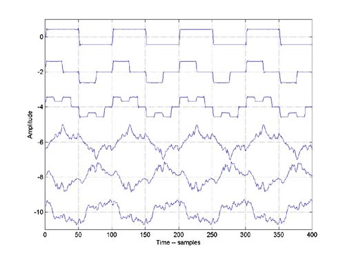
From this we may be tempted to decide that in general we are not all that sensitive to phase. However, this is not always the case. Figures 3 and 4 show another set of waveforms. This set is similar to those shown in figures 1 and 2, but with many more harmonics.
The top is a bandlimited square wave. The next two signals have the same frequency components, but with the phases of those components changed in different ways. The other three signals have randomized phase for each of the harmonics.
These six signals can be downloaded as files:
- cphase1.wav
- cphase2.wav
- cphase3.wav
- cphase4.wav
- cphase5.wav
- cphase6.wav
- You may need to "right-click" or "click and hold" to download the files.
Take a minute to download these files and listen to them. With these files, you may hear significant differences between the signals, even in steady-state – especially at higher listening levels. Part of the reason for this is that the human ear is not completely linear, so some harmonic content is actually ‘manufactured’ in the ear. This content will be sensitive to the time-domain behavior of the waveform.
People tend to be most sensitive to phase distortion in the presence of transients. The two files ‘drum.wav’ and ‘drumAP.wav’ contain a drum track.
- drum.wav
- drumAP.wav
- You may need to "right-click" or "click and hold" to download the files.
The file ‘drum.wav’ is the dry recorded track, and ‘drumAP.wav’ is the same track passed through an allpass filter, which has a completely flat magnitude response, but warps the phase. The audible artifacts from the phase warping are perceived by most people as time-domain problems. The warped-signal has a more diffused, almost reverberant sound, while the dry track sounds much tighter. As a rule of thumb, if the phase-warping smears the signal by less than 10mS, the artifacts will not be offensive. Since the amount of time-smearing is defined as the phase of the response at a given frequency divided by that frequency measured in radians/second, for a given phase shift, artifacts may be more noticeable at lower frequencies.
Stay tuned for Part II, where we will introduce linear phase, and cover its uses, advantages and drawbacks.