Wiggly Frequency Response and the Cooper Time Cube
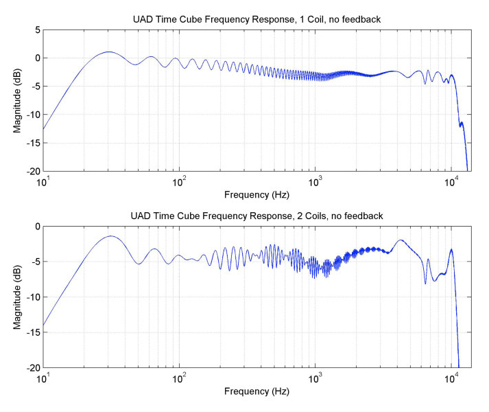
The Cooper Time Cube is famous for its spectacular short delay and doubling effects, and its uncanny ability to always sit perfectly in the mix. As you can see in Figure 1, the Cooper Time Cube plug-in’s delay element has a rather “wiggly” frequency response. The high-frequency and large-scale, low-frequency variations are modeling hardware frequency responses that are largely due to the characteristics of the transducers and the cavities in which they sit. (The interested reader is directed to <choose a url for the patent (#03789328) from among the various online patent retrieval sites> for intricate discussion of the methods used to tune the cavities' mechanical system to help flatten the general frequency response.) The fast “wiggles,” on the other hand, are directly related to the delay, and how the Time Cube implements it.
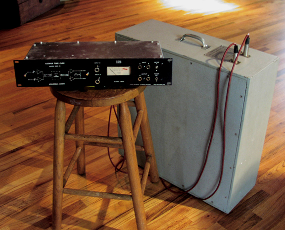
The Time Cube hardware implements a delay using a long, hose-like tube, injecting the audio at one end and sensing it at the other end. (Shure microphone capsules, such as would be found in an SM57, are used on both ends, as both a speaker and a pickup.) The delay is due to the finite speed of sound, because it will take a certain amount of time for the sound waves to propagate down the tube. Figure 2 shows a simplified diagram of the sound propagation in one channel of the Time Cube hardware.
The Time Cube hardware implements a delay using a long, hose-like tube, injecting the audio at one end and sensing it at the other end.
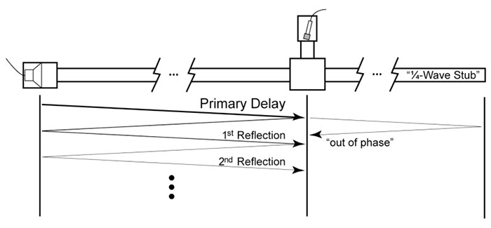
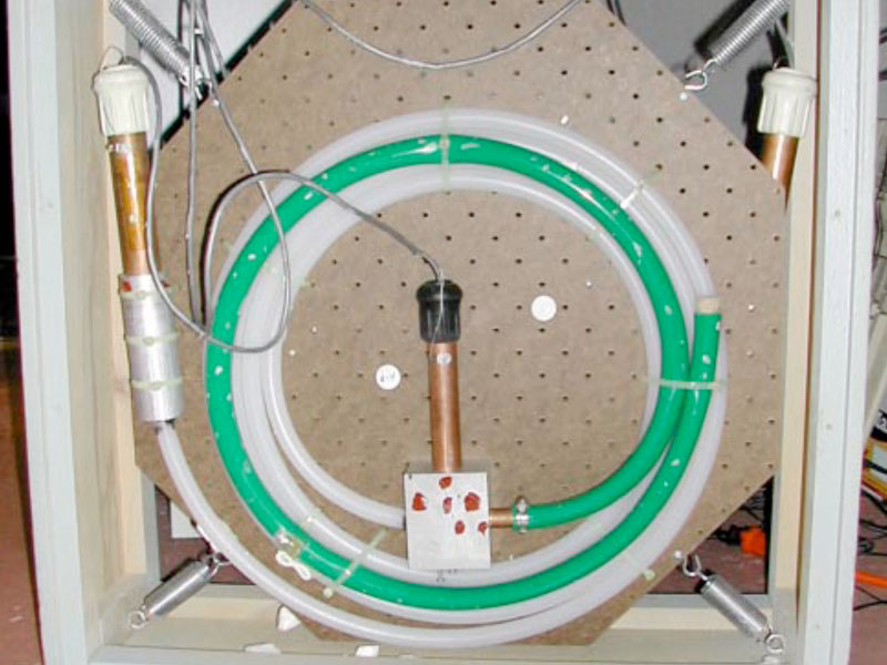
One of the primary problems that Putnam and Cooper had to deal with was how to get the tube to act as merely a simple delay. Sound waves will partially reflect off any change in the properties of the tube (such as diameter), and simply terminating the tube is a major change in the tube properties and will result in almost complete reflection. As such, the sound waves will reflect off the ends of the tube, bouncing back and forth many times. Although this might be a desirable effect sometimes (a delay with feedback around it gives the same kind of effect and is quite popular), it would be very difficult to try to remove those reflections from the sound if one did not want the reflections, or wanted reflections that decayed faster than the tube’s natural decay rate. One of the techniques they employed was a “quarter-wave stub”: Another tube attached at the end of the tube, with some internal damping, and tuned to a particular length such that the waves which return to the junction from bouncing off the end of the stub are 180 degrees out of phase with the reflections in the main delay tube, at the frequencies that are most affected by the reflections (harmonics of 1/delay) and thus should act to cancel the reflections. The stub is the green tube that can be seen in Figure 3. Unfortunately, they were not able to completely cancel the reflections, and so a small bump exists in the impulse response 2×delay after than the main delay (about 32ms and 28ms later, respectively, for the two channels in the hardware). This bump is the cause of the “wiggles.” Further reflections also occur in the response, but they are doubly (and triply, etc.) attenuated by the additional partial reflections, and so are sufficiently small as to no longer have an appreciable effect.
To illustrate the effect of a reflection on the response, we will experiment with two simplified systems, and show how the responses change by adding delayed pulses to their impulse responses. The first example system is a simple bandpass system which is essentially flat, but with roll-off at high and low frequencies. The second system is a randomly generated filter, which also has the same high- and low-frequency roll-offs (see Figs. 4 and 5).
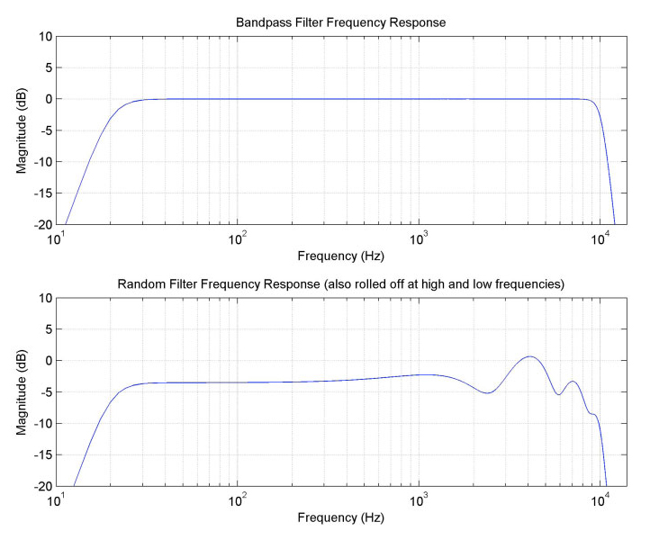
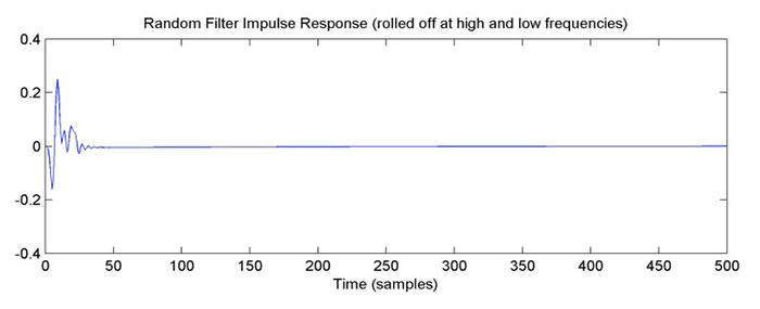
(note the example sample rate of 44 kHz)
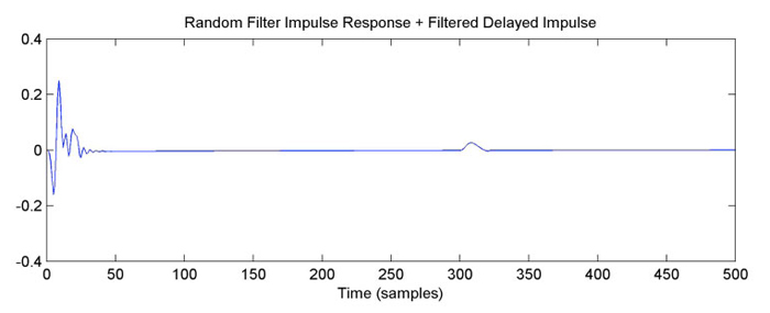
Now, we add a lower-energy delayed pulse into the system, as seen in Figure 6.
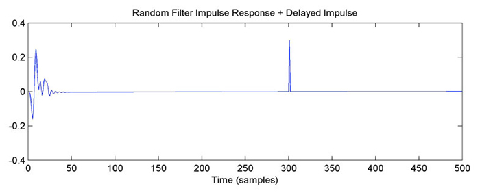
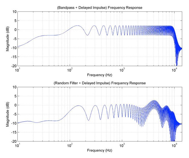
The effect on the frequency response is to add a regular wiggle to it (see Fig. 7). The wiggle is periodic in the frequency domain, at a “frequency” determined by the amount of delay between the basic system’s impulse and the new impulse. The wiggle doesn’t appear periodic in these graphs because the frequency axis is logarithmic. The depth of the wiggles depends on the relative sizes of the main filter response and the delayed response. In this case, the delayed pulse is about 30% the size of the main pulse, so at the frequencies where the main pulse and the delayed pulse constructively interfere, the gain is raised by 1.3 (about 2.3 dB higher), and where they destructively interfere, the gain is reduced by 0.7 (about 3 dB lower). For the random filter case, the size of the wiggle partly depends on the local frequency response gain. For example, at frequencies where the base response is less, then the delayed pulse’s response is a larger percentage of the base response, so the wiggle is a larger (for example, around 2.5 kHz, or just below 10 kHz).
The added impulse was a pure digital impulse, so it had the same energy at all frequencies, and the wiggle had a relatively constant size (other than where the base response was significantly far from 0 dB). Now, if the delayed pulse is also filtered, the wiggle size will vary with frequency, according to the relative ratio of the base system’s gain and the delayed pulse’s gain (and according to the relative phase responses, but we won’t go into that in this discussion). In Figure 8, we change the delayed pulse to be lowpass filtered, with a cutoff frequency of 2 kHz.
In Figure 9, we see that the wiggle gets smaller at frequencies where the pulse is strongly attenuated (because the delayed signal at those frequencies is much smaller relative to the main signal). The reflected pulses in the Time Cube end up pretty strongly lowpass filtered, and we see a similar reduction in the wiggle at high frequencies as in Figure 1.
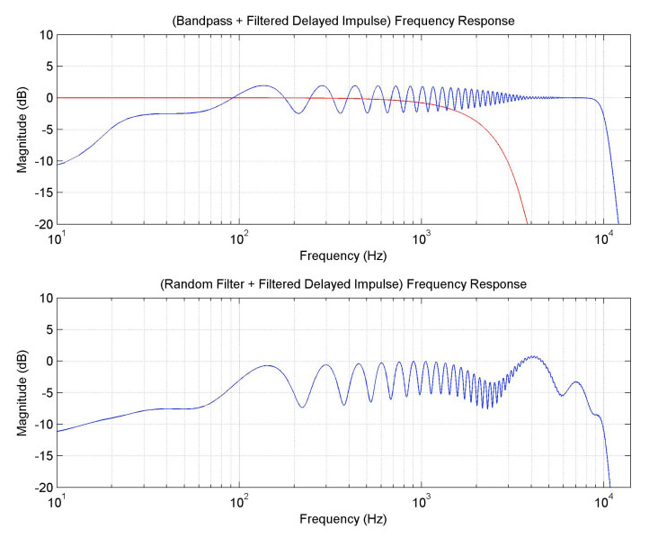
The frequency response of the filtration is shown in red in the top graph.
The “2-coil” mode of the plug-in models the case where the user patches the output of Channel A through Channel B in the hardware, to get a longer delay. Because the delays have the reflections, these will interact when the channels are cascaded. The primary effect is that there will be two reflection bumps in the impulse response rather than one. Because the hardware delays are approximately 14ms and 16ms, the two bumps are about 4ms apart (because the reflections are delayed by 2x the 14ms and 16ms delays). We now add a second bump to the example responses (see Fig. 10).
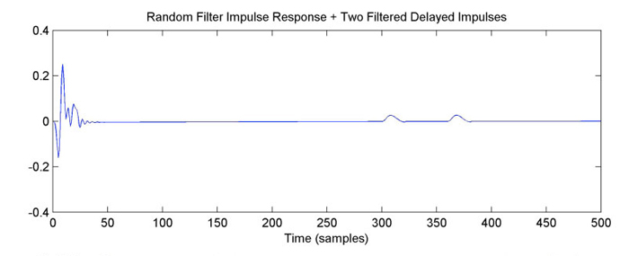
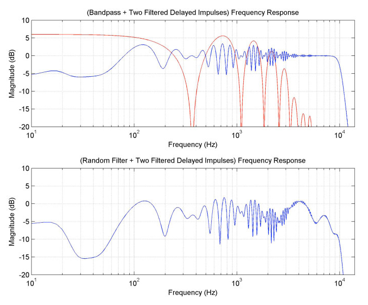
The frequency response of the combined delayed pulses is shown in red in the top graph.
As one might infer from the previous discussion, the two bumps, taken together, will have a frequency response that has a regular set of peaks and dips (enveloped by the lowpass filtration). In this case, since the two bumps have the same size and filtration, they will completely cancel at the dips, so their combined response will go all the way down to zero. This can be seen in the red curve in Figure 11, which is the frequency response of just the two pulses. Because the size of the resulting wiggles in the total responses is based on the relative gains of the base response and the delayed response, the wiggle gets larger and smaller periodically where the delayed pulses’ response rises and dips, respectively. This pattern can also be seen in the frequency response for the 2-coil mode in Figure 1.
In conclusion, a combination of effects combine to shape the frequency responses of the Time Cube’s core delay elements, and contribute to the “character” of the sound. When used together with further plug-in capabilities, such as feedback, these small details in the frequency response can become even more complex and interesting.
— Dr. Dave Berners
Read More
5-Min UAD Tips: Cooper Time Cube Plug-In
In this 5-Minute UAD Tip, you’ll learn how to add width to a mono keyboard track, add vibey slapback to guitars, and synchronized delay tails on a vocal with the UAD Cooper Time Cube MkII Delay plug-in.
Mixing Cold War Kids’ “First” with UAD Plug‑Ins
Lars Stalfors (The Mars Volta, Marnie Stern) breaks down how he and Dann Gallucci (TV On The Radio, Tim Curran) used UAD Powered Plug-Ins on the track “First” from the Cold War Kids’ album, Hold My Home.


