Volume 2, Number 9, October/November (AES) 2004
[UA Universe] [Ask the Doctors] [Digital Discourse] [Analog Obsession]
[Support Report] [The Channel] [Digi-Talk] [Analog Dialog] [Featured Promotion]
[Graphic-Rich WebZine]
[Back Issues] [UA Home]
 |
|
Professor Vaccuum Tube
|
Ask the Doctors: The Professor of Pomp Pontificates on Preamps (and Compressors of the Tube Variety)
Q: Professor Vacuum Tube, How Do You Get Off Calling it an LA-610?
A: Well, boys and girls, let's just calm down a bit. I believe you mean, "Say Professor, would you please tell us about the circuit topology used in the LA-610 All Tube Recording Channel." Sure, I'm happy to talk about topography. It conjures up wonderful images of lush, verdant rolling hills with herds of triodes and pentodes grazing peacefully. I can still picture those noble beasts, high upon a bluff, with their warm glowing eyes shining through the darkness and hear the melodious sounds they always seem to produce throughout the evening.
Oh... circuit topology...right. The LA-610 All Tube Recording Channel is based on the circuit topology of the 610 preamp and the LA-2A compressor. We wanted to bring all the compressor sounds of the LA-2A into a 610 Mic Preamp. Our guiding design theme was "never send a Transistor to do a Triode's job." First, we'll look at the topologies of the 610 and the LA-2A, and then see how they fit into the LA-610.
“So, what's the topology of the LA-610? Well, those clever engineering devils at UA ripped the 610 mic preamp circuit topology down the middle, inserted the LA-2A reduction circuit topology, and added a triode stage to keep EQ ahead of the compressor.”
The 610 Topology
The 610 mic pre circuit is found in Universal Audio's 2-610, M-610 and 6176, as well as classic console modules. The 610 circuit topology, shown below, is a two tube pre amp with input and output transformers. For simplicity, I don't show the input pad, phantom supply, and other lesser details.
A balanced input signal runs through a pad, loading, and switching network and finds it's way to the 610 input transformer. We pick up the action there in the figure. The input transformer gives some voltage gain and provides a matched, unbalanced signal to the first active gain stage, a 12AX7 dual triode. This stage provides a Gain Switch to position the input signal level into a desired region of the tube's dynamic range, which gives user control over 'tube sound'. (Ah... the sounds of a triode herd carried along on a warm evening breeze...)
So, the first stage output passes through the Level control, which determines the input level to the second stage, thereby setting overall output level. This output stage, a 6072 dual triode, provides a fixed gain and is used to implement the HF/LF Shelving Equalizers. It also provides the drive to the output transformer, which sets impedance and level for signal output.
In the LA-610, we started with this topology and inserted a LA-2A style compressor. The idea was to maintain the sonics of the 610 and provide T4 based compression along with it. The blue shaded portions of the 610 figure above shows the 610 sections that are used in the LA-610.
The LA-2A Topology
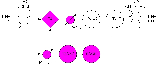
Here we show the LA-2A circuit topology. The line-input signal passes through an input transformer for balanced to unbalanced impedance matching and gain. The T4 electro-luminescent attenuator is next in the signal path and provides the compressor/limiter gain reduction so familiar to LA-2A users. A Gain control is next in the signal path and sets the drive to the output chain, and therefore, the output level. The 12AX7 dual triode stage follows and provides fixed, active gain. The output stage, a 12BH7 dual triode, gives the drive level for the balanced line level output transformer.
The compressor side chain sets the limiting threshold by varying the signal level to the T4. The input to the side chain is picked off ahead of the T4 and a Gain reduction control, controlling threshold, and setting the level into the side chain amps. The 12AX7 dual triode which follows, provides side chain gain. The next stage, a 6AQ5 pentode, drives the EL panel in the T4 to control the gain reduction.
The T4 optical attenuator is a close-coupled EL panel and photo resistor. As the panel gets brighter, the photo resistor's impedance drops and, in a voltage divider circuit, reduces the signal to the Gain pot. This is the heart of the LA-2A compression character.
For the LA-610, we used the essential T4 topology from the LA-2, as shown in the purple highlighted sections of the above diagram
The LA-610 Topology
So now we have the topology of the LA-610 with the 610 derived topology shown in blue and the LA-2A derived topology shown in purple. The entire 610 input section is used here, with an additional 12AX7 used to implement its HF/LF EQ stage ahead of the compressor. Following this mic pre section, the essential LA-2A derived T4 side chain topology is employed to provide the classic LA-2A compressor sound and gain reduction. Then follows a 610 output section, comprised of a 6072 to provide make-up gain, and a 610 output transformer to drive the line output.
We took care in the design of the LA-610 gain structure to make sure that the same signal levels are present at the T4 inputs of both the LA-2A and the LA-610 in unity gain configurations. Combining this with the same side chain topology in each unit, there's a lot of LA-2A in the LA-610. The T4 optical attenuators in both use the same components, but in different packages as we discuss below.
The T4-A
Used in the LA-2A, the electroluminescent panel and photo resistors are sandwiched around a PCB and pinned out through an octal tube socket. A metal can cover completes the light tight package. The T4 plugs into the back of the LA-2A but is too tall for the inside of a 2U chassis like the LA-610.
The T4-UA
The T4 in the LA-610 uses the same components and PCB sandwich as in the LA-2A, but the module is rotated to the horizontal and plugs into the main board inside the chassis. A light tight cover screws into the main board to complete the package.
Conclusion
So, what's the topology of the LA-610? Well, those clever engineering devils at UA ripped the 610 mic preamp circuit topology down the middle, inserted the LA-2A reduction circuit topology, and added a triode stage to keep EQ ahead of the compressor. Of course they also slipped it all into an economical package, fiddled around with wires and stuff, and even listened to it a lot. So, a tip of the professor's hat goes to Si, Sean, Tim, Dave, Joe, and Dennis at UA, and my father's 75-year-old Versalog.
The LA-610 results from joining the two topologies, stripping out the Split/Join multi-connect stuff, and making a clean-path, dedicated mic pre/compressor, bringing LA-2 compression into our tube mic-pre products. Keep an eye on UA, because the Sales and Marketing folks can hear the rumbling herds of triodes and pentodes.
So, till next time kids, keep your heaters glowing and your pins straight.
-Professor Vacuum Tube