Volume 3, Number 10, December 2005
[UA Universe] [Ask the Doctors] [Artist Interview] [Analog Obsession]
[Support Report] [The Channel] [Plug-In Power] [Playback] [Featured Promotion]
[Graphic-Rich WebZine]
[Back Issues] [UA Home]
 |
|
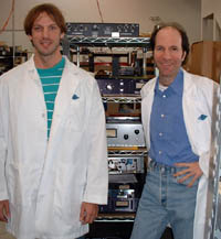
Dr. David Berners (left) is the Universal Audio Director of Algorithm Development; Dr. Jonathan Abel is the co-founder and CTO
|
by Dr. Dave Berners
This month, the Doctors answer the question, "How does the Mid-Side (MS) microphone technique work?" You'll also want to take a look at this issue's Analog Obsession, which includes step-by-step instructions for putting together a Mid-Side setup. Please note that this article has the Mid + Side signal as facing right, whereas the "Analog Obsession" article has Mid + Side facing left. The important thing to remember is that whichever way the normal front of the figure-8 side mic is facing in the recording, that is the direction the Mid + Side signal should be panned.
The Mid-Side technique allows a stereo recording to be made using two coincident mics. The recording is encoded as two audio channels, which can later be mixed to produce the left and right signals. Mixing the two recorded channels with varying amplitudes produces differing degrees of stereo field separation, varying from pure mono to something resembling what would be obtained by using two coincident hyper-cardioid mics pointing about 125 degrees away from each other. Mixing the two recorded signals is similar to what is done inside mics that have electrically switchable polar patterns, with the benefit that it can be done after the recording is made.
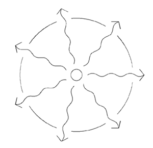
In order to understand the mechanics of how the Mid-Side technique works, let us first examine how soundfields are produced, and how they are detected by microphones. Consider the sound source in Fig. 1.
 |
|
Figure 1: Isotropic source radiating a spherical wave
|
This source (the small circle at the center of the figure) radiates with equal intensity in all directions. Because the speed of sound is the same in every direction, the disturbance created by this source has what is known as a spherical wavefront: If a sphere is constructed centered at the source, the acoustic pressure at every point on the surface of the sphere will be the same, at every instant in time. The sphere is known as an isophase surface. If multiple (omnidirectional) microphones are placed anywhere along the surface of the sphere, all of the microphones will record identical signals from this source.
“Mixing the two recorded signals is similar to what is done inside mics that have electrically switchable polar patterns, with the benefit that it can be done after the recording is made.”
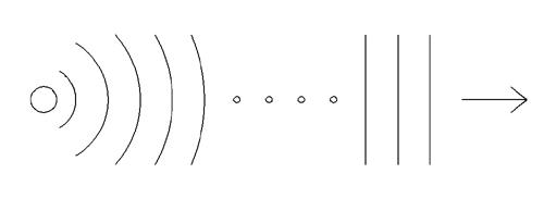
As the distance from the sound source increases, the radius of the spherical wavefront increases, and the curvature of that wavefront becomes smaller and smaller. Figure 2 shows successive wavefronts emanating form a point-like source.
 |
|
Figure 2: Plane wave approximation for spherical disturbance
|
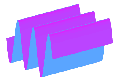
If the ellipses in the middle of Fig. 2 are taken to represent a large distance, the lines on the right side of Fig. 2 represent the wavefronts, or isophase surfaces, of the disturbance, far from the source. Here, the radii of the spherical surfaces have become very large, so that their curvature is very small. The isophase surfaces eventually approach planes. Thus, as the distance from the source grows, the disturbance produced by the point-like source begins to approximate plane waves. Figure 3 shows a representation of a plane wave.
 |
|
Figure 3: Plane wave
|
In general, an acoustic disturbance will consist of some acoustic pressure, which is a function of space and time, p(x,y,z,t). The pressure will vary over all three coordinates in space, and will vary with time. Plane waves, however, are highly constrained acoustic disturbances in that they are one-parameter disturbances: For plane waves, the pressure is only a function of one spatial dimension, and that dimension is the direction in which the wave is traveling. For example, a plane wave moving along the x axis will have pressure that can be represented as p(x,t). The pressure will be constant over all values of y and z; if a plane wave is moving north, then the pressure will be the same regardless of altitude or east-west position.
Because plane waves are well-defined and relatively simple, and are good approximations for the behavior of sound far from the source, microphone polar patterns are almost universally expressed based upon responses to plane waves.
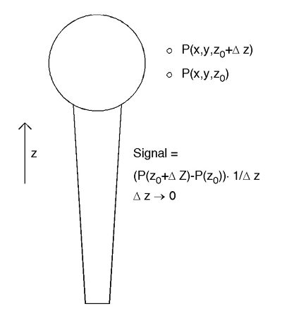
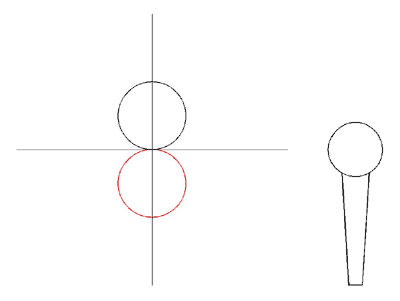
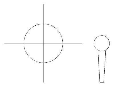
The most common type of "directional" mic is the pressure-gradient mic, which responds to differences in pressure over a region that is small compared to the wavelengths of the sounds being recorded. Usually, the front and back of the microphone's capsule will both be exposed, so that the net force moving the capsule is the difference between the pressure at the front and the pressure at the back of the capsule. Because the capsule has some (non-zero) thickness, in essence the pressure is being differentiated along the capsule's axis. Figure 4 shows a representation of a pressure-gradient mic.
 |
|
Figure 4: Directional mic
|
From this figure, it is clear that what is being measured is effectively the difference (by subtraction) in pressure between two different points in space. It should be noted that pressure-gradient mics are intrinsically directional, as shown in Figs. 5 and 6.
 |
|
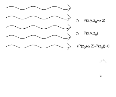
Figure 5: Plane wave arriving perpendicular to axis of pressure-gradient mic
|
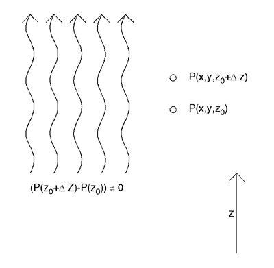 |
|
Figure 6: Plane wave arriving along axis of pressure-gradient mic
|
In Fig. 5, with the arriving plane wave traveling in the x-direction and the microphone pointed in the z-direction, it is clear that a zero-valued signal will be recorded, because the pressure from the plane wave is constant in the z-direction. In Fig. 6, with the plane wave moving along the axis of the microphone, the pressure due to the plane wave varies as a function of z. Here, the difference in pressure at points z and z+Δ will not be zero. Obviously, the microphone of Fig. 4 has sensitivity to the direction of incidence of sound.
As it turns out, this sensitivity to direction of incidence can be easily computed for plane waves, with the result shown in Fig. 7.
 |
|
Figure 7: Polar pattern for pressure-gradient microphone
|
The polar response for a pressure-gradient mic is proportional to cos(Θ), where Θ is the angle of incidence. Figure 7 shows the amplitude of the response as a function of angle, with the radius of the curve being proportional to the amplitude. Negative (out of phase) response is shown in red. For waves approaching along the mic axis from the front, the amplitude has a maximum. For waves approaching directly from the side of the mic, the polar response has a null. For waves approaching from the back, the response again has a maximum, but this time with negative phase. The pattern shown in Fig. 7 is known as a figure-of-eight polar pattern.
Microphones with switchable polar patterns usually use weighted combinations of the pattern of Fig. 7 with the omnidirectional pattern, shown in Fig. 8.
 |
|
Figure 8: Omnidirectional mic
|
As can be seen from the figure, the omnidirectional mic has the same sensitivity regardless of the direction of propagation of the sound. The omni mic simply records the pressure over time at a single point in space.
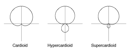
By combining (adding) the responses of Figs. 7 and 8 in different ratios, most of the common directional patterns can be generated. Figure 9 shows three popular polar patterns.
 |
|
Figure 9: Common polar patterns
|
The cardioid is formed by adding equal parts of the figure-of-eight and omnidirectional patterns. As can be seen, the cardioid has a null for sound approaching directly from the rear. This is due to the fact that the figure-of-eight pattern has an amplitude of one with reversed phase, and the omni pattern has an in-phase amplitude of one. When the two signals are summed equally, a null is produced. The hypercardioid pattern is formed by adding figure-of-eight and omni responses in a ratio of three to one, and the supercardioid is formed by using a ratio of five to three.
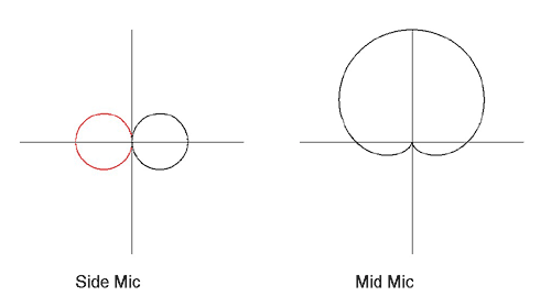
The Mid-Side technique uses a combination of figure-of-eight and cardioid mics, which are set up with their axes perpendicular to each other, as shown in Fig. 10.
 |
|
Figure 10: Mid-Side mic patterns
|
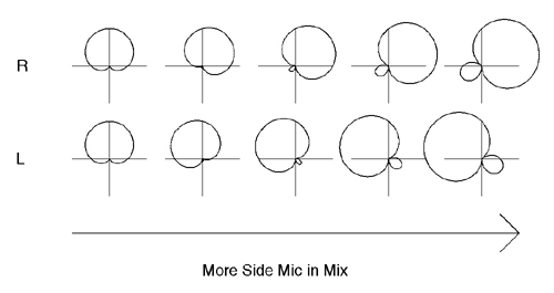
The "side" mic is a figure-of-eight pattern, and the "mid" mic is a cardioid. Usually, during recording, the signals from these mics are kept separate. Later, in mixing, they can be combined according to taste. For the placement shown, the front of the "side" mic is facing toward the right, so the right audio channel will be formed by adding the mic signals (m + s) in some ratio. The left audio channel will be formed by subtracting the signals (m - s). This is accomplished by mixing the two signals together after reversing the phase of the "side" mic. Depending upon the ratio with which the two signals are mixed, various directional preferences can be obtained after the fact, as shown in Fig. 11.
 |
|
Figure 11: Mid-Side polar responses
|
The plots in Fig. 11 show the polar responses obtained for the left and right audio channels by mixing the mid and side mics in different ratios. If no side mic is mixed in, the responses on the left of the figure are obtained. As more side mic is used, we progress through the plots until, with equal amounts of mid and side mics mixed together, we arrive at the plots on the right hand side of the figure. These plots are similar to the hypercardioid response, centered at about plus and minus sixty degrees off-axis.
As noted above, the Mid mic response is a cardioid, which is formed by adding equal parts omni and figure-of-eight response. Thus, the expression for the cardioid is Am=0.5+0.5cos(Θ). The figure-of-eight pattern, since the side mic is placed at ninety degrees, will be As=sin(Θ). The plots shown in Fig. 11 will be of the form Ams=α(0.5+0.5cos(Θ))+βsin(Θ), with β =0 on the left, and β=α on the right.
A similar technique could be used with a figure-of-eight mic and an omni, both pointing along the same axis, to generate different members of the cardioid family after the fact. Thus, by recording two channels of audio, it would be possible to mix the signals to produce the response that would be obtained from a cardioid, hypercardioid, or supercardioid mic (or anything in between).